
There are several reasons why land surveyors are increasingly adding drones to their portfolio of instruments.
Firstly, using a drone can vastly reduce the time spent collecting accurate data. By acquiring raster data from the sky – in the form of geo-referenced digital aerial images, with resolutions as sharp as 1.5 cm (0.6 in) per pixel – you can gather millions of data points in one short flight.
More time still can be saved by using a survey-grade drone eith GNSS/RTK receiver systems are effectively flying rovers, capable of receiving data corrections streamed from a base station or via VRS to achieve absolute X, Y, Z accuracy of down to 3 cm (1.2 in) – without needing Ground Control Points.
With collection made so simple, you can focus your energy on using and analysing data, rather than working out how to gather it.
With such a large increase in the amount of physical data being collected, this does mean an increase in office time spent processing and utilising this data. However this expansion is cancelled out many times over by the huge time savings a drone produces out in the field. Many of senseFly’s surveying customers say, for example, that large jobs that once took weeks can now be completed in just a few days, and that a week’s worth of traditional data collection is now achieved in just one day.
Last but not least, less time spent on the ground means staff safety is improved by minimising risk to surveying teams when measuring sites such as mines, unstable slopes and transport routes. Simply choose take-off and landing locations that are out of harm’s way.
Flight planning
-
Choose/import base map
-
Highlight coverage area (rectangle/polygon)
-
Set desired Ground Sampling Distance (i.e. 5 cm (2 in) / pixel)
-
Flight altitude defined automatically as a result (e.g. 5 cm/pixel = 162 m altitude using default eBee WX camera)
-
This altitude determines maximum single-flight coverage possible
-
Automatic definition of flight lines & image capture points
-
-
Set image overlap
-
Necessary for stereo coverage
-
-
Define safe landing zone
Setting of on-site GCPs
-
For absolute X,Y, Z accuracy of down to 3 cm / 5 cm (1.2 in / 2 in)
-
No GCPs required, to achieve similar accuracy, if using eBee RTK
-
Optimal size & shape of GCP targets defined by GSD of imagery
Flight
-
Autonomous flight
-
Monitor progress/change flight plan via flight control software
-
Automated landing as per defined landing zone
Import Images
-
On-board SD card contains images and flight log (.bbx file)
-
Images geo-tagged according to flight log during importation
-
Generate Quality Report on site to verify quality and coverage
Generation of orthomosaics and 3D point clouds
-
Using post-flight photogrammetry software
-
Relative orthomosaic/3D model accuracy: 1-3x GSD
Analysis/production of deliverables
-
Creation of break lines, reference points, digital elevation models, contour lines
-
Calculation & analysis of volumes and stockpiles
-
Export of output files (geoTIFF, obj, dxf, shape, LAS, KML tiles etc.) to third-party software as required (see below)
Final report/deliverable creation in third-party software

3D Land Survey & Mapping
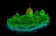
Architectural 3D Mapping

Volumetric measuring

Urban Planning
Land Cover & vegitation analysis

Construction Site Land Survey

Planning 3D CAD onto countored map
3D Underwater Mapping using towed-Sonor

Planning new structures on 3D map

Shaddow analysis of building construction
Aerial Survey & Mapping

